Component which maintains a setpoint temperature
 A digital thermostat
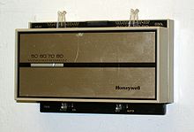
 Honeywell's "The Round" model T87 thermostat, one of which is in the collection of the Smithsonian.
 A touch screen thermostat
 An electronic thermostat in a retail store
A thermostat is a regulating device component which senses the temperature of a physical system and performs actions so that the system's temperature is maintained near a desired setpoint.
Thermostats are used in any device or system that heats or cools to a setpoint temperature. Examples include building heating, central heating, air conditioners, HVAC systems, water heaters, as well as kitchen equipment including ovens and refrigerators and medical and scientific incubators. In scientific literature, these devices are often broadly classified as thermostatically controlled loads (TCLs). Thermostatically controlled loads comprise roughly 50% of the overall electricity demand in the United States.[1]
A thermostat operates as a "closed loop" control device, as it seeks to reduce the error between the desired and measured temperatures. Sometimes a thermostat combines both the sensing and control action elements of a controlled system, such as in an automotive thermostat. The word thermostat is derived from the Greek words θερμÏŒς thermos, "hot" and στατÏŒς statos, "standing, stationary".
A thermostat exerts control by switching heating or cooling devices on or off, or by regulating the flow of a heat transfer fluid as needed, to maintain the correct temperature. A thermostat can often be the main control unit for a heating or cooling system, in applications ranging from ambient air control to automotive coolant control. Thermostats are used in any device or system that heats or cools to a setpoint temperature. Examples include building heating, central heating, and air conditioners, kitchen equipment such as ovens and refrigerators, and medical and scientific incubators.
Construction and control
[edit]
Thermostats use different types of sensors to measure temperatures and actuate control operations. Mechanical thermostats commonly use bimetallic strips, converting a temperature change into mechanical displacement, to actuate control of the heating or cooling sources. Electronic thermostats, instead, use a thermistor or other semiconductor sensor, processing temperature change as electronic signals, to control the heating or cooling equipment.
Conventional thermostats are example of "bang-bang controllers" as the controlled system either operates at full capacity once the setpoint is reached, or keeps completely off. Although it is the simplest program to implement, such control method requires to include some hysteresis in order to prevent excessively rapid cycling of the equipment around the setpoint. As a consequence, conventional thermostats cannot control temperatures very precisely. Instead, there are oscillations of a certain magnitude, usually 1-2 °C.[2] Such control is in general inaccurate, inefficient and may induce more mechanical wear; it however, allows for more cost-effective compressors compared to ones with continuously variable capacity.[3][clarification needed]
Another consideration is the time delay of the controlled system. To improve the control performance of the system, thermostats can include an "anticipator", which stops heating/cooling slightly earlier than reaching the setpoint, as the system will continue to produce heat for a short while.[4] Turning off exactly at the setpoint will cause actual temperature to exceed the desired range, known as "overshoot". Bimetallic sensors can include a physical "anticipator", which has a thin wire touched on the thermostat. When current passes the wire, a small amount of heat is generated and transferred to the bimetallic coil. Electronic thermostats have an electronic equivalent.[5]
When higher control precision is required, a PID or MPC controller is preferred. However, they are nowadays mainly adopted for industrial purposes, for example, for semiconductor manufacturing factories or museums.
Early technologies included mercury thermometers with electrodes inserted directly through the glass, so that when a certain (fixed) temperature was reached the contacts would be closed by the mercury. These were accurate to within a degree of temperature.
Common sensor technologies in use today include:
These may then control the heating or cooling apparatus using:
- Direct mechanical control
- Electrical signals
- Pneumatic signals
Possibly the earliest recorded examples of thermostatic control were built by a Dutch innovator, Cornelis Drebbel (1572–1633), about 1620 in England. He invented a mercury thermostat to regulate the temperature of a chicken incubator.[6] This is one of the first recorded feedback-controlled devices.
Modern thermostatic control was developed in the 1830s by Andrew Ure (1778–1857), a Scottish chemist. The textile mills of the time needed a constant and steady temperature to operate optimally, so Ure designed the bimetallic thermostat, which would bend as one of the metals expanded in response to the increased temperature and cut off the energy supply.[7]
Warren S. Johnson (1847–1911), of Wisconsin, patented a bi-metal room thermostat in 1883, and two years later sought a patent for the first multi-zone thermostatic control system.[8][9] Albert Butz (1849–1905) invented the electric thermostat and patented it in 1886.
One of the first industrial uses of the thermostat was in the regulation of the temperature in poultry incubators. Charles Hearson, a British engineer, designed the first modern incubator for eggs, which was taken up for use on poultry farms in 1879.[10]
Mechanical thermostats
[edit]
This covers only devices which both sense and control using purely mechanical means.
Domestic water and steam based central heating systems have traditionally been controlled by bi-metallic strip thermostats, and this is dealt with later in this article. Purely mechanical control has been localised steam or hot-water radiator bi-metallic thermostats which regulated the individual flow. However, thermostatic radiator valves (TRV) are now being widely used.
Purely mechanical thermostats are used to regulate dampers in some rooftop turbine vents, reducing building heat loss in cool or cold periods.
Some automobile passenger heating systems have a thermostatically controlled valve to regulate the water flow and temperature to an adjustable level. In older vehicles the thermostat controls the application of engine vacuum to actuators that control water valves and flappers to direct the flow of air. In modern vehicles, the vacuum actuators may be operated by small solenoids under the control of a central computer.
 Car engine thermostat
Perhaps the most common example of purely mechanical thermostat technology in use today is the internal combustion engine cooling system thermostat, used to maintain the engine near its optimum operating temperature by regulating the flow of coolant to an air-cooled radiator. This type of thermostat operates using a sealed chamber containing a wax pellet that melts and expands at a set temperature. The expansion of the chamber operates a rod which opens a valve when the operating temperature is exceeded. The operating temperature is determined by the composition of the wax. Once the operating temperature is reached, the thermostat progressively increases or decreases its opening in response to temperature changes, dynamically balancing the coolant recirculation flow and coolant flow to the radiator to maintain the engine temperature in the optimum range.
On many automobile engines, including all Chrysler Group and General Motors products, the thermostat does not restrict flow to the heater core. The passenger side tank of the radiator is used as a bypass to the thermostat, flowing through the heater core. This prevents formation of steam pockets before the thermostat opens, and allows the heater to function before the thermostat opens. Another benefit is that there is still some flow through the radiator if the thermostat fails.
Shower and other hot water controls
[edit]
A thermostatic mixing valve uses a wax pellet to control the mixing of hot and cold water. A common application is to permit operation of an electric water heater at a temperature hot enough to kill Legionella bacteria (above 60 °C, 140 °F), while the output of the valve produces water that is cool enough to not immediately scald (49 °C, 120 °F).
A wax pellet driven valve can be analyzed through graphing the wax pellet's hysteresis which consists of two thermal expansion curves; extension (motion) vs. temperature increase, and contraction (motion) vs. temperature decrease. The spread between the up and down curves visually illustrate the valve's hysteresis; there is always hysteresis within wax driven valves due to the phase transition or phase change between solids and liquids. Hysteresis can be controlled with specialized blended mixes of hydrocarbons; tight hysteresis is what most desire, however some applications require broader ranges. Wax pellet driven valves are used in anti scald, freeze protection, over-temp purge, solar thermal energy or solar thermal, automotive, and aerospace applications among many others.
Thermostats are sometimes used to regulate gas ovens. It consists of a gas-filled bulb connected to the control unit by a slender copper tube. The bulb is normally located at the top of the oven. The tube ends in a chamber sealed by a diaphragm. As the thermostat heats up, the gas expands applying pressure to the diaphragm which reduces the flow of gas to the burner.
Pneumatic thermostats
[edit]
A pneumatic thermostat is a thermostat that controls a heating or cooling system via a series of air-filled control tubes. This "control air" system responds to the pressure changes (due to temperature) in the control tube to activate heating or cooling when required. The control air typically is maintained on "mains" at 15-18 psi (although usually operable up to 20 psi). Pneumatic thermostats typically provide output/ branch/ post-restrictor (for single-pipe operation) pressures of 3-15 psi which is piped to the end device (valve/ damper actuator/ pneumatic-electric switch, etc.).[11]
The pneumatic thermostat was invented by Warren Johnson in 1895[12] soon after he invented the electric thermostat. In 2009, Harry Sim was awarded a patent for a pneumatic-to-digital interface[13] that allows pneumatically controlled buildings to be integrated with building automation systems to provide similar benefits as direct digital control (DDC).
Electrical and analog electronic thermostats
[edit]
 Bimetallic thermostat for buildings.
Water and steam based central heating systems have traditionally had overall control by wall-mounted bi-metallic strip thermostats. These sense the air temperature using the differential expansion of two metals to actuate an on/off switch.[14] Typically the central system would be switched on when the temperature drops below the setpoint on the thermostat, and switched off when it rises above, with a few degrees of hysteresis to prevent excessive switching. Bi-metallic sensing is now being superseded by electronic sensors. A principal use of the bi-metallic thermostat today is in individual electric convection heaters, where control is on/off, based on the local air temperature and the setpoint desired by the user. These are also used on air-conditioners, where local control is required.
This follows the same nomenclature as described in Relay § Terminology and Switch § Contact terminology. A thermostat is considered to be activated by thermal energy, thus “normal” refers to the state in which temperature is below the setpoint.
- "NO" stands for "normally open". This is the same as "COR" ("close on rise"). May be used to start a fan when it is becoming hot, and to stop the fan when it has become cold enough.
- "NC" stands for "normally closed". This is the same as "OOR" ("open on rise"). May be used to start a heater when it is becoming cold, and to stop the heater when it has become warm enough.
- "CO" stands for "change over". This serves both as "NO" and "NC". May be used to start a fan when it is becoming hot, but also (on the opposite terminal), to start a heater when it is becoming cold.
Any leading number stands for number of contact sets, like "1NO", "1NC" for one contact set with two terminals. "1CO" will also have one contact set, even if it is a switch-over with three terminals.
Simple two wire thermostats
[edit]
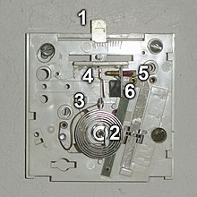 Millivolt thermostat mechanism
The illustration is the interior of a common two wire heat-only household thermostat, used to regulate a gas-fired heater via an electric gas valve. Similar mechanisms may also be used to control oil furnaces, boilers, boiler zone valves, electric attic fans, electric furnaces, electric baseboard heaters, and household appliances such as refrigerators, coffee pots and hair dryers. The power through the thermostat is provided by the heating device and may range from millivolts to 240 volts in common North American construction, and is used to control the heating system either directly (electric baseboard heaters and some electric furnaces) or indirectly (all gas, oil and forced hot water systems). Due to the variety of possible voltages and currents available at the thermostat, caution must be taken when selecting a replacement device.
- Setpoint control lever. This is moved to the right for a higher temperature. The round indicator pin in the center of the second slot shows through a numbered slot in the outer case.
- Bimetallic strip wound into a coil. The center of the coil is attached to a rotating post attached to lever (1). As the coil gets colder the moving end — carrying (4) — moves clockwise.
- Flexible wire. The left side is connected via one wire of a pair to the heater control valve.
- Moving contact attached to the bimetal coil. Thence, to the heater's controller.
- Fixed contact screw. This is adjusted by the manufacturer. It is connected electrically by a second wire of the pair to the thermocouple and the heater's electrically operated gas valve.
- Magnet. This ensures a good contact when the contact closes. It also provides hysteresis to prevent short heating cycles, as the temperature must be raised several degrees before the contacts will open. As an alternative, some thermostats instead use a mercury switch on the end of the bimetal coil. The weight of the mercury on the end of the coil tends to keep it there, also preventing short heating cycles. However, this type of thermostat is banned in many countries due to its highly and permanently toxic nature if broken. When replacing these thermostats they must be regarded as chemical waste.
Not shown in the illustration is a separate bimetal thermometer on the outer case to show the actual temperature at the thermostat.
Millivolt thermostats
[edit]
As illustrated in the use of the thermostat above, all of the power for the control system is provided by a thermopile which is a combination of many stacked thermocouples, heated by the pilot light. The thermopile produces sufficient electrical power to drive a low-power gas valve, which under control of one or more thermostat switches, in turn controls the input of fuel to the burner.
This type of device is generally considered obsolete as pilot lights can waste a surprising amount of gas (in the same way a dripping faucet can waste a large amount of water over an extended period), and are also no longer used on stoves, but are still to be found in many gas water heaters and gas fireplaces. Their poor efficiency is acceptable in water heaters, since most of the energy "wasted" on the pilot still represents a direct heat gain for the water tank. The Millivolt system also makes it unnecessary for a special electrical circuit to be run to the water heater or furnace; these systems are often completely self-sufficient and can run without any external electrical power supply. For tankless "on demand" water heaters, pilot ignition is preferable because it is faster than hot-surface ignition and more reliable than spark ignition.
Some programmable thermostats - those that offer simple "millivolt" or "two-wire" modes - will control these systems.
24-volt thermostats
[edit]
The majority of modern heating/cooling/heat pump thermostats operate on low voltage (typically 24 volts AC) control circuits. The source of the 24 volt AC power is a control transformer installed as part of the heating/cooling equipment. The advantage of the low voltage control system is the ability to operate multiple electromechanical switching devices such as relays, contactors, and sequencers using inherently safe voltage and current levels.[15] Built into the thermostat is a provision for enhanced temperature control using anticipation.
A heat anticipator generates a small amount of additional heat to the sensing element while the heating appliance is operating. This opens the heating contacts slightly early to prevent the space temperature from greatly overshooting the thermostat setting. A mechanical heat anticipator is generally adjustable and should be set to the current flowing in the heating control circuit when the system is operating.
A cooling anticipator generates a small amount of additional heat to the sensing element while the cooling appliance is not operating. This causes the contacts to energize the cooling equipment slightly early, preventing the space temperature from climbing excessively. Cooling anticipators are generally non-adjustable.
Electromechanical thermostats use resistance elements as anticipators. Most electronic thermostats use either thermistor devices or integrated logic elements for the anticipation function. In some electronic thermostats, the thermistor anticipator may be located outdoors, providing a variable anticipation depending on the outdoor temperature.
Thermostat enhancements include outdoor temperature display, programmability, and system fault indication. While such 24 volt thermostats are incapable of operating a furnace when the mains power fails, most such furnaces require mains power for heated air fans (and often also hot-surface or electronic spark ignition) rendering moot the functionality of the thermostat. In other circumstances such as piloted wall and "gravity" (fanless) floor and central heaters the low voltage system described previously may be capable of remaining functional when electrical power is unavailable.
There are no standards for wiring color codes, but convention has settled on the following terminal codes and colors.[16][17] In all cases, the manufacturer's instructions should be considered definitive.
| Terminal code |
Color |
Description |
| R |
Red |
24 volt (Return line to appliance; often strapped to Rh and Rc) |
| Rh |
Red |
24 volt HEAT load (Return line Heat) |
| Rc |
Red |
24 volt COOL load (Return line Cool) |
| C |
Black/Blue/Brown/Cyan |
24 volt Common connection to relays |
| W / W1 |
White |
Heat |
| W2 |
Varies/White/Black |
2nd Stage / Backup Heat |
| Y / Y1 |
Yellow |
Cool |
| Y2 |
Blue/Orange/Purple/Yellow/White |
2nd Stage Cool |
| G |
Green |
Fan |
| O |
Varies/Orange/Black |
Reversing valve Energize to Cool (Heat Pump) |
| B |
Varies/Blue/Black/Brown/Orange |
Reversing valve Energize to Heat (Heat Pump) or Common |
| E |
Varies/Blue/Pink/Gray/Tan |
Emergency Heat (Heat Pump) |
| S1/S2 |
Brown/Black/Blue |
Temperature Sensor (Usually outdoors on a Heat Pump System) |
| T |
Varies/Tan/Gray |
Outdoor Anticipator Reset, Thermistor |
| X |
Varies/Black |
Emergency Heat (Heat Pump) or Common |
| X2 |
Varies |
2nd stage/emergency heating or indicator lights |
| L |
Varies |
Service Light |
| U |
Varies |
User programmable (usually for humidifier) |
| K |
Yellow/Green |
Combined Y and G |
| PS |
Varies |
Pipe Sensor for two pipe heat/cool systems |
| V |
Varies |
Variable speed (many can function as W2) |
Older, mostly deprecated designations:
| Terminal code |
Description |
| 5 / V |
24 volt ac supply |
| 4 / M |
24 volt HEAT load |
| 6 / blank |
Not heat to close valve |
| F |
Cool fan relay or Fault light |
| G |
Heat fan relay |
| H |
Heat valve |
| M |
Heat Pump compressor |
| P |
Heat Pump defrost |
| R |
Heat pump reversing valve |
| VR |
24 volt auxiliary heat |
| Y |
Auxiliary heat |
| C |
Clock power (usually two terminals) or Cool relay |
| T |
Transformer common |
| Z |
Fan power source for "Auto" connection |
Line-voltage thermostats
[edit]
Line voltage thermostats are most commonly used for electric space heaters such as a baseboard heater or a direct-wired electric furnace. If a line voltage thermostat is used, system power (in the United States, 120 or 240 volts) is directly switched by the thermostat. With switching current often exceeding 40 amperes, using a low voltage thermostat on a line voltage circuit will result at least in the failure of the thermostat and possibly a fire. Line voltage thermostats are sometimes used in other applications, such as the control of fan-coil (fan powered from line voltage blowing through a coil of tubing which is either heated or cooled by a larger system) units in large systems using centralized boilers and chillers, or to control circulation pumps in hydronic heating applications.
Some programmable thermostats are available to control line-voltage systems. Baseboard heaters will especially benefit from a programmable thermostat which is capable of continuous control (as are at least some Honeywell models), effectively controlling the heater like a lamp dimmer, and gradually increasing and decreasing heating to ensure an extremely constant room temperature (continuous control rather than relying on the averaging effects of hysteresis). Systems which include a fan (electric furnaces, wall heaters, etc.) must typically use simple on/off controls.
Digital electronic thermostats
[edit]
 Residential digital thermostat
 Lux Products' Model TX9000TS Touch Screen Thermostat.
 Lux Products WIN100 Heating & Cooling Programmable Outlet Thermostat shown with control door closed and open.
Newer digital thermostats have no moving parts to measure temperature and instead rely on thermistors or other semiconductor devices such as a resistance thermometer (resistance temperature detector). Typically one or more regular batteries must be installed to operate it, although some so-called "power stealing" digital thermostats (operated for energy harvesting) use the common 24-volt AC circuits as a power source, but will not operate on thermopile powered "millivolt" circuits used in some furnaces. Each has an LCD screen showing the current temperature, and the current setting. Most also have a clock, and time-of-day and even day-of-week settings for the temperature, used for comfort and energy conservation. Some advanced models have touch screens, or the ability to work with home automation or building automation systems.
Digital thermostats use either a relay or a semiconductor device such as triac to act as a switch to control the HVAC unit. Units with relays will operate millivolt systems, but often make an audible "click" noise when switching on or off.
HVAC systems with the ability to modulate their output can be combined with thermostats that have a built-in PID controller to achieve smoother operation. There are also modern thermostats featuring adaptive algorithms to further improve the inertia prone system behaviour. For instance, setting those up so that the temperature in the morning at 7 a.m. should be 21 °C (69.8 °F), makes sure that at that time the temperature will be 21 °C (69.8 °F), where a conventional thermostat would just start working at that time. The algorithms decide at what time the system should be activated in order to reach the desired temperature at the desired time.[18] Other thermostat used for process/industrial control where on/off control is not suitable the PID control can also makes sure that the temperature is very stable (for instance, by reducing overshoots by fine tuning PID constants for set value (SV)[19] or maintaining temperature in a band by deploying hysteresis control.[20])
Most digital thermostats in common residential use in North America and Europe are programmable thermostats, which will typically provide a 30% energy savings if left with their default programs; adjustments to these defaults may increase or reduce energy savings.[21] The programmable thermostat article provides basic information on the operation, selection and installation of such a thermostat.
Thermostats and HVAC operation
[edit]
Ignition sequences in modern conventional systems
[edit]
- Gas
-
- Start draft inducer fan/blower (if the furnace is relatively recent) to create a column of air flowing up the chimney
- Heat ignitor or start spark-ignition system
- Open gas valve to ignite main burners
- Wait (if furnace is relatively recent) until the heat exchanger is at proper operating temperature before starting main blower fan or circulator pump
- Oil
- Similar to gas, except rather than opening a valve, the furnace will start an oil pump to inject oil into the burner
- Electric
- The blower fan or circulator pump will be started, and a large electromechanical relay or TRIAC will turn on the heating elements
- Coal, grain or pellet
- Generally rare today (though grains such as corn, wheat, and barley, or pellets made of wood, bark, or cardboard are increasing in popularity); similar to gas, except rather than opening a valve, the furnace will start a screw to drive coal/grain/pellets into the firebox
With non-zoned (typical residential, one thermostat for the whole house) systems, when the thermostat's R (or Rh) and W terminals are connected, the furnace will go through its start-up procedure and produce heat.
With zoned systems (some residential, many commercial systems — several thermostats controlling different "zones" in the building), the thermostat will cause small electric motors to open valves or dampers and start the furnace or boiler if it is not already running.
Most programmable thermostats will control these systems.
Combination heating/cooling regulation
[edit]
Depending on what is being controlled, a forced-air air conditioning thermostat generally has an external switch for heat/off/cool, and another on/auto to turn the blower fan on constantly or only when heating and cooling are running. Four wires come to the centrally-located thermostat from the main heating/cooling unit (usually located in a closet, basement, or occasionally in the attic): One wire, usually red, supplies 24 volts AC power to the thermostat, while the other three supply control signals from the thermostat, usually white for heat, yellow for cooling, and green to turn on the blower fan. The power is supplied by a transformer, and when the thermostat makes contact between the 24 volt power and one or two of the other wires, a relay back at the heating/cooling unit activates the corresponding heat/fan/cool function of the unit(s).
A thermostat, when set to "cool", will only turn on when the ambient temperature of the surrounding room is above the set temperature. Thus, if the controlled space has a temperature normally above the desired setting when the heating/cooling system is off, it would be wise to keep the thermostat set to "cool", despite what the temperature is outside. On the other hand, if the temperature of the controlled area falls below the desired degree, then it is advisable to turn the thermostat to "heat".
Heat pump regulation
[edit]
Thermostat design
The heat pump is a refrigeration based appliance which reverses refrigerant flow between the indoor and outdoor coils. This is done by energizing a reversing valve (also known as a "4-way" or "change-over" valve). During cooling, the indoor coil is an evaporator removing heat from the indoor air and transferring it to the outdoor coil where it is rejected to the outdoor air. During heating, the outdoor coil becomes the evaporator and heat is removed from the outdoor air and transferred to the indoor air through the indoor coil. The reversing valve, controlled by the thermostat, causes the change-over from heat to cool. Residential heat pump thermostats generally have an "O" terminal to energize the reversing valve in cooling. Some residential and many commercial heat pump thermostats use a "B" terminal to energize the reversing valve in heating. The heating capacity of a heat pump decreases as outdoor temperatures fall. At some outdoor temperature (called the balance point) the ability of the refrigeration system to transfer heat into the building falls below the heating needs of the building. A typical heat pump is fitted with electric heating elements to supplement the refrigeration heat when the outdoor temperature is below this balance point. Operation of the supplemental heat is controlled by a second stage heating contact in the heat pump thermostat. During heating, the outdoor coil is operating at a temperature below the outdoor temperature and condensation on the coil may take place. This condensation may then freeze onto the coil, reducing its heat transfer capacity. Heat pumps therefore have a provision for occasional defrost of the outdoor coil. This is done by reversing the cycle to the cooling mode, shutting off the outdoor fan, and energizing the electric heating elements. The electric heat in defrost mode is needed to keep the system from blowing cold air inside the building. The elements are then used in the "reheat" function. Although the thermostat may indicate the system is in defrost and electric heat is activated, the defrost function is not controlled by the thermostat. Since the heat pump has electric heat elements for supplemental and reheats, the heat pump thermostat provides for use of the electric heat elements should the refrigeration system fail. This function is normally activated by an "E" terminal on the thermostat. When in emergency heat, the thermostat makes no attempt to operate the compressor or outdoor fan.
Thermostat location
[edit]
The thermostat should not be located on an outside wall or where it could be exposed to direct sunlight at any time during the day. It should be located away from the room's cooling or heating vents or device, yet exposed to general airflow from the room(s) to be regulated.[22] An open hallway may be most appropriate for a single zone system, where living rooms and bedrooms are operated as a single zone. If the hallway may be closed by doors from the regulated spaces then these should be left open when the system is in use. If the thermostat is too close to the source controlled then the system will tend to "short a cycle", and numerous starts and stops can be annoying and in some cases shorten equipment life. A multiple zoned system can save considerable energy by regulating individual spaces, allowing unused rooms to vary in temperature by turning off the heating and cooling.
Setback temperature
[edit]
HVAC systems take a long time, usually one to several hours, to cool down or warm up the space from near outdoor conditions in summer or winter. Thus, it is a common practice to set setback temperatures when the space is not occupied (night and/or holidays). On the one hand, compared with maintaining at the original setpoint, substantial energy consumption can be saved.[23] On the other hand, compared with turning off the system completely, it avoids room temperature drifting too much from the comfort zone, thus reducing the time of possible discomfort when the space is again occupied. New thermostats are mostly programmable and include an internal clock that allows this setback feature to be easily incorporated.
It has been reported that many thermostats in office buildings are non-functional dummy devices, installed to give tenants' employees an illusion of control.[24][25] These dummy thermostats are in effect a type of placebo button. However, these thermostats are often used to detect the temperature in the zone, even though their controls are disabled. This function is often referred to as "lockout".[26]
Notes and references
[edit]
- ^ Energy Information Administration, Residential energy consumption survey, U.S. Dept. Energy, Washington, DC, Tech. Rep., 2001.
- ^
thermostathub (June 26, 2023). "Easy Home Heating: Get Started with the Danfoss Wireless Thermostat". Thermostat Hub. Retrieved October 23, 2023.
- ^ Homod, Raad Z.; Gaeid, Khalaf S.; Dawood, Suroor M.; Hatami, Alireza; Sahari, Khairul S. (August 2020). "Evaluation of energy-saving potential for optimal time response of HVAC control system in smart buildings". Applied Energy. 271: 115255. Bibcode:2020ApEn..27115255H. doi:10.1016/j.apenergy.2020.115255. S2CID 219769422.
- ^ Roots, W. K. (1962). "An introduction to the assessment of line-voltage thermostat performance for electric heating applications". Transactions of the American Institute of Electrical Engineers, Part II: Applications and Industry. 81 (3): 176–183. doi:10.1109/TAI.1962.6371813. ISSN 0097-2185. S2CID 51647958.
- ^ James E. Brumbaugh, AudelHVAC Fundamentals: Volume 2: Heating System Components, Gas and Oil Burners, and Automatic Controls, John Wiley & Sons, 2004 ISBN 0764542079 pp. 109-119
- ^ "Tierie, Gerrit. Cornelis Drebbel. Amsterdam: HJ Paris, 1932" (PDF). Retrieved May 3, 2013.
- ^ "An Early History Of Comfort Heating". The NEWS Magazine. Troy, Michigan: BNP Media. November 6, 2001. Retrieved November 2, 2014.
- ^ "Thermostat Maker Deploys Climate Control Against Climate Change". America.gov. Archived from the original on April 18, 2009. Retrieved October 3, 2009.
- ^ "Johnson Controls Inc. | History". Johnsoncontrols.com. November 7, 2007. Retrieved October 3, 2009.
- ^ Falk, Cynthia G. (2012). Barns of New York: Rural Architecture of the Empire State (paperback) (First ed.). Ithaca, New York: Cornell University Press (published May 1, 2012). ISBN 978-0-8014-7780-5. Retrieved November 2, 2014.
- ^ "Dr-Fix-It Explains a Common Pneumatic Comfort Control Circuit". dr-fix-it.com. RTWEB. 2005. Archived from the original on December 6, 2017. Retrieved November 2, 2014.
- ^ Fehring, T.H., ed., Mechanical Engineering: A Century of Progress, NorCENergy Consultants, LLC, October 10, 1980 - Technology & Engineering, p. 22
- ^ "Pneumatic-to-digital devices, systems and methods" (PDF).
- ^ Salazar, Diet (October 21, 2019). "Thermostats: Everything You Need to Know". Engineer Warehouse. Retrieved March 12, 2021.
- ^ Electrical potentials at and below 24 volts are classed as "Safety Extra-Low Voltage" under most electrical codes when supplied through an isolation transformer.
- ^ Sawyer, Doc. "Thermostat Wire Color Codes". dr-fix-it.com. Archived from the original on September 23, 2015. Retrieved March 7, 2015.[1]
- ^ Transtronics, Inc. "Thermostat signals and wiring". wiki.xtronics.com. Retrieved March 7, 2015.
- ^ Honeywell smart response technology
- ^ "Smart PID temperature control". smartpid.com. September 19, 2016. Retrieved October 10, 2018.
- ^ "Temperature Controllers Using Hysteresis". panasonic.com. October 18, 2011. Retrieved October 10, 2018.
- ^ "Summary of Research Findings From the Programmable Thermostat Market" (PDF). Energy Star. Retrieved March 12, 2021.
- ^ KMC Controls. "Room Sensor and Thermostat: Mounting and Maintenance Application Guide" (PDF). Retrieved April 12, 2021.
- ^ Moon, Jin Woo; Han, Seung-Hoon (February 1, 2011). "Thermostat strategies impact on energy consumption in residential buildings". Energy and Buildings. 43 (2): 338–346. Bibcode:2011EneBu..43..338M. doi:10.1016/j.enbuild.2010.09.024. ISSN 0378-7788.
- ^ Sandberg, Jared (January 15, 2003). "Employees Only Think They Control Thermostat". The Wall Street Journal. Retrieved September 2, 2009.
- ^ Katrina C. Arabe (April 11, 2003). ""Dummy" Thermostats Cool Down Tempers, Not Temperatures". Retrieved February 13, 2010.
- ^ Example datasheet of current art thermostat, exhibiting lockout functionality : http://cgproducts.johnsoncontrols.com/MET_PDF/12011079.pdf
| |
Fundamental
concepts |
|
| Technology |
|
| Components |
|
Measurement
and control |
|
Professions,
trades,
and services |
|
Industry
organizations |
|
| Health and safety |
|
| See also |
|